| ID |
Date |
Author |
Subject |
|
179
|
Tue, 4.12.2012 17:45:25 |
A.Ivashkin | A-detector |
A-detector at 800V works well, but the peaks are close to pedestal. The voltages at both PMTs are increased to 870 V.
At 20.30 the voltages were increased to 1020 Volts |
|
178
|
Tue, 4.12.2012 13:50:29 |
Zoltan Fodor | measurements of the time of beam counters |
I checked on the QA the counter histograms, and realized the missing time information for S11-S12 ans S11-S2.
The S11-S12 was a contact problem.
The time of the S11 is changed relative to the pPb run, because of the smalest HV on S11. I took out ~8ns cabel from the stop signal(S2)
and the measured value gone back to the time window. |
|
177
|
Mon, 3.12.2012 18:14:48 |
D.Jokovic | TOF status at the start of Be run |
| https://na61db.cern.ch:8443/elog/TOF+logbook/12 |
|
176
|
Mon, 3.12.2012 17:19:43 |
A.Ivashkin | A-detector |
| A-detector is installed at ~11.00 a.m. The preliminary HV was set at 800 V for both PMTs. The further HV adjustment would be done at beam. |
|
175
|
Mon, 3.12.2012 16:48:23 |
O.Petukhov | PSD |
PSD platform moved to the run position (13cm to Jura https://na61db.cern.ch:8443/elog/Experts+logbook/117). Y-position at 0 cm. Z-position - at 71 cm from TPC hut.
Power up, HV settings checked.
psd-for-na61 trigger ready.
Switched to the main DAQ. |
|
174
|
Mon, 3.12.2012 10:54:38 |
S. Kowalski | Z Det |
Quartz Z Det on beam position. HV for ZdetQ1 2000 V, ZdetQ2 1910
ZF: 13:13
The CEDAR taken out from the beam line
The new quadrupole magnets installed between the BPD2 and BPD3
The target holder aligned wirh V1 counters.
The position of the BPD2 and BPD3 is measured
The voltages on the beam counters set as where at last Be run in 2011. |
|
173
|
Fri, 30.11.2012 14:53:08 |
A.Laszlo | Pressure loss in VTPC chilled water circuit. |
| Due to the above reason the readout electronics power supply tripped, |
|
172
|
Tue, 27.11.2012 12:54:35 |
A.Aduszkiewicz | TPC voltage ramping up status |
amplification voltage/drift voltage
|
| VTPC-1 | VTPC-2 | MTPC-L | MTPC-R | GAP TPC |
| |
27/11/2012 12:50 | 0V/1kV | 0V/1kV | 0V/1kV | 0V/1kV | 0V/1kV |
| |
28/11/2012 11:30 | 0V/3kV | 0V/3kV | 0V/5kV | 0V/5kV | 0V/3kV |
| |
28/11/2012 14:25 | 0V/5kV | 0V/5kV | 0V/8kV | 0V/8kV | 0V/5kV |
| |
28/11/2012 16:50 | 0V/8kV | 0V/8kV | 0V/12kV | 0V/12kV | 0V/7kV |
| |
29/11/2012 12:50 | 100V/13kV | 100V/13kV | 100V/19kV | 100V/19kV | 100V/10.2kV | potential strips turned on; full drift voltage |
| |
29/11/2012 16:55 | 300V/13kV | 300V/13kV | 300V/19kV | 300V/19kV | 300V/10.2kV |
| |
30/11/2012 11:40 | 710/680V/13kV | 560V/13kV | 560/490V/19kV | 560/490V/19kV | 620V/10.2kV | amplification voltages 500V below the nominal value |
| |
30/11/2012 19:40 | 910/880V/13kV | 760V/13kV | 760/690V/19kV | 760/690V/19kV | 820V/10.2kV | amplification voltages 300V below the nominal value |
| |
1/12/2012 16:05 | 1010/980V/13kV | 860V/13kV | 860/790V/19kV | 860/790V/19kV | 920V/10.2kV | amplification voltages 200V below the nominal value |
| |
2/12/2012 15:40 | 1110/1080V/13kV | 960V/13kV | 960/890V/19kV | 960/890V/19kV | 1020V/10.2kV | amplification voltages 100V below the nominal value |
| |
2/12/2012 16:30 | 1160/1130V/13kV | 1010V/13kV | 1010/940V/19kV | 1010/940V/19kV | 1070V/10.2kV | amplification voltages 50V below the nominal value |
| |
|
|
|
171
|
Mon, 8.10.2012 08:19:05 |
A.Laszlo | TPC potential strips were off for the whole run |
| A,Aduszkiewicz found that all the potential strips were off for the whole Autumn p+Pb run. |
| Attachment 1: id171-2012-10-08-082232.png
|

|
| Attachment 2: id171-2012-10-08-084436.png
|

|
|
170
|
Mon, 8.10.2012 08:18:17 |
A.Aduszkiewicz | End of p+Pb run - TPC HV status |
Drift voltage:
VTPCs: 13 kV
MTPCs: 19 kV
GAP TPC: 10200V
Amplification voltage:
VTPC-1: 1210V/1180V
VTPC-2: 1060V
MTPCs: 1060V/990V
GAP TPC: 1170V
LMPD: 1150V/400V
I found the potential strips OFF!!!
The screenshots are attached to the next logbook entry (https://na61db.cern.ch:8443/elog/Experts+logbook/171) due to elog limitations. |
|
169
|
Wed, 3.10.2012 15:57:39 |
A.Aduszkiewicz | GAP TPC HV increased by another 10V |
| On Zoltan's request GAP TPC sense wire voltage were increased to 1170V, since the measured signals were still too low. |
|
168
|
Wed, 3.10.2012 15:35:26 |
Z. Fodor | MTPC hut temperature |
At 13.30 we increased the incoming air temprature by 1 C degree. I learned from the guy, they modified
the regulation some times ago but recently, and now the preciseness of the regulation is 2 degree.
It is possible the improvment and we have to discuss with him team leader. |
|
167
|
Tue, 2.10.2012 14:16:27 |
A.Aduszkiewicz | no helium between VT2 and MT |
| We realised that the aquarium ("sac") between VTPC2 and MTPC hut was not filled with helium before this (p+Pb) run. We decided to leave it like that in order to keep constant conditions during the data taking. |
|
166
|
Mon, 1.10.2012 14:06:41 |
A.Aduszkiewicz | GAP TPC HV increased by 10V |
| GAP TPC chamber HV was increased by 10V to 1160V, because the signals were too low. |
|
165
|
Sat, 29.09.2012 17:14:38 |
Zoltan Fodor | Temperature in the MTPC hut |
After increasing the chield water flow, the temperature going too low and instable.
On the climat unit 16 degree was set, now I put 20. |
|
164
|
Tue, 25.09.2012 21:01:58 |
Zoltan Fodor | TOF readout problem |
The TOF read out crashed, could not initialize the create No5.
Reconnected the VSBI bus in the old configuration. second slot for TOFL-R and second one for TOFL.
I switched on the FTOF readout create as well.
|
|
163
|
Fri, 21.09.2012 21:43:27 |
Zoltan Fodor | DAQ problem |
The dt s11-s12 contact repaired
from the dt S11-s2 8ns taken out, to be in the range the signals
The TOF readout take 0 data from TOF 5 and 6 bosbank. In the initialization
stage not found any readable unit. Changing the cables on the lda unit
the all of the TOF system could read out. |
|
162
|
Fri, 21.09.2012 18:52:50 |
A. Marcinek | Problems with BPD1 signals |
| see https://na61db.cern.ch:8443/elog/BPD+logbook/65 |
|
161
|
Fri, 21.09.2012 13:16:10 |
D.Jokovic | TOF HV status at the start of p+Pb run |
On TOF-R, the distributors #1.1, #1.2 & #1.3 in the crate 1 didn't work. High voltage for those PMTs supplied by new, custom made distributors, in new crate.
The distributor #2.9 in crate 2 replaced due to undervoltage on all channels.
On TOF-L, the distributor #4.6 (several undervoltage channels) is replaced with repaired one. Also the pin #16 connected to this distributor pulled out (Ovc).
From HV point of view, 54 pixels on TOF-L don't work, and 17 pixels on TOF-R. |
|
160
|
Thu, 20.09.2012 21:04:58 |
A.Laszlo | LMPD operational settings for p+Pb physics run |
- Gas: BPS gas, Ar/CO2 (85%/15%) on both chambers. We have a single input, then a splitting for the two chambers. We have flow meter on the single input, and on the two outputs.
- Gas flow: 8l/h in each chamber's output, 20l/h in the two chamber's input before splitting.
- Drift field voltage: -4kV on each chamber.
- Drift field current: 51.9mA (LMPD-J), 46.5mA (LMPD-S). Current is measured to be linear as a function of voltage (resistor chain).
- Field and Sense Wire voltages: -400V (LMPD-J-Field), +1150V (LMPD-J-Sense), -400V (LMPD-S-Field), +1150V (LMPD-S-Sense). See also: https://na61db.cern.ch:8443/elog/Experts+logbook/120920_210519/id160-2012-09-20-210514.png.png?thumb=1
- Field and Sense Wire currents: 0.4nA (LMPD-J-Field), 1.0nA (LMPD-S-Field), 29.12uA (LMPD-J-Sense), 29.75uA (LMPD-S-Sense). Currents of Field Wires are within measurement errors. Currents on Sense Wires are due to resistor chain and is measured to be linear as a function of input voltage.
- Target material: Pb.
- Target thickness: 2 x 0.5mm lead foil.
- He flow of the target atmosphere: 4l/h. |
| Attachment 1: id160-2012-09-20-210514.png
|

|
|
159
|
Thu, 20.09.2012 19:10:59 |
Zoltan Fodor | Magnet problem on VTX1 again |
ZF: The VTX1 magnet is quenched !!!!!!! some times around 6 o'clock
in the crio logbook 18:01 started the quench signal, arrived to 61 mV in 1 minute and go down in 3 minutes.
Around the same time, /could be a litle beat earlier/ the pression on the He flow
true the bobines increased.
Must be checked tomorrow Morning with crio guys and Alexey. |
|
158
|
Thu, 20.09.2012 14:18:15 |
Zoltan Fodor | Magnet settings |
Set the current on the magnets for 160 GeV/c configuration
VTX1 set value: 5012.6A measured value: 5011.6A
VTX2 set value: 3773.5A measured: 3778.2A |
|
157
|
Thu, 20.09.2012 00:20:20 |
A. Marcinek | BPD HV |
| 00:15 (AM) Set BPD HV to 1750V on all chambers |
|
156
|
Wed, 19.09.2012 15:36:53 |
A.Laszlo | He bag between MTPCL and R |
| He bag between MPTC-L and R was not connected. Connected it and started inflating with 50l/h. |
|
155
|
Tue, 18.09.2012 17:51:56 |
A.Laszlo | Target alignment |
LMPD target was installed and aligned to nominal position +/-0.5mm, and measured.
BPD3 was put to nominal position by eye and measured.
V1 is not yet aligned / measured. |
|
154
|
Mon, 17.09.2012 14:05:42 |
A. Marcinek | BPD3 on beam and gas flow started in all BPDs |
| see https://na61db.cern.ch:8443/elog/BPD+logbook/62 |
|
153
|
Mon, 17.09.2012 10:19:40 |
A.Laszlo | VTX1 test |
S4 was put in 160GeV/c position.
Magnet area was cleared.
Magnet power supply switched on.
He leak rate is stable and pumpable.
During VTX1 ramp, before and around 2kA short timescale spikes were seen. Amplitude of spikes ranged up to 0.5V. After 2.5kA the amplitude of spikes significantly decreased, almost vanished.
14:45: VTX1 magnet test successfully finished, VTX1 is down. Now ramping VTX2.
17:28: VTX2 magnet test successfully finished, VTX2 is also down.
Software upgrade for magnet power converter is scheduled tomorrow. |
|
152
|
Mon, 17.09.2012 10:18:38 |
A.Laszlo | Target holder change to LMPD |
On 14 Septermber 2012 we removed VTX1 magnet scaffolding. Small He leak is seen since 13 September, but leak rate is stable.
On 14 September 2012 we removed with Martin Wensveen the solid target holder and installed LMPD. |
|
151
|
Fri, 24.08.2012 16:29:23 |
A.Laszlo | VTX1 magnet leak welded, box closed |
VTX1 magnet joint was welded and brazed in place.
Leak test with He detector performed.
Leak test with He detector repeated 2 times after heat shock with liquid nitrogen.
New joint was found leak tight.
The vacuum box was closed.
Vacuum pump down began. |
|
150
|
Tue, 21.08.2012 14:40:29 |
A.Laszlo | VTX1 top insulator box closed |
The VTX1 top insulator box (where current leads connect to) has been closed.
The connector piece to replace the leaking part in bottom box of VTX1 is being manufactured. |
|
149
|
Mon, 13.08.2012 16:00:06 |
Z.fodor | PSD movement |
I moved the PSD to the parking position. move down by 472mm and to Jura 340mmm
Checking on the magnet leak is going on, trying to determine the leak position
by filling the thermal screen by air and after adding He and measuring the time
when it is appering inside the vacuum.
The measured volume of the thermal screen is 7l.
|
|
148
|
Wed, 8.08.2012 13:53:21 |
Z. Fodor | S5 position |
| The S5 counter was survey by the geometers at the position -61.5, 7.9 |
|
147
|
Mon, 6.08.2012 13:24:11 |
Z. Fodor | Magnet heating |
From NA49 VTX@ reparation we found: 60 heating current at 20V is 215K.
62A at 28V is 270K
using this information calculated the actual temperature of the coill
with linear inter/extrapolation. |
| Attachment 1: id147-2012-08-06-135710.png
|

|
|
146
|
Mon, 6.08.2012 10:25:15 |
A.Laszlo | Beam counters settings for 2012 VTX2-only run |
|
| Attachment 1: id146-2012-08-06-102522.png
|

|
|
145
|
Mon, 6.08.2012 08:43:42 |
A.Aduszkiewicz | TPC HV setting summer 2012 |
Wire voltages in the attachment.
Drift voltages:
VTPCs: 13kV
MTPCs: 19kV
GAP TPC: 10.2kV |
| Attachment 1: id145-2012-08-06-084247.png
|

|
|
144
|
Thu, 2.08.2012 08:57:06 |
Z. Fodor | Problem with na61conv |
During the MD the na61conv hanged up, was no connections and the terminal also was not working. I restarted with the reset button.
The network 1 is not working, i changed the network cable to 2 ethernet connection, after is working. |
|
143
|
Mon, 30.07.2012 13:52:55 |
Z. Fodor | Warning up VTX1 magnet |
Starting from 26.07.2012 we measured the resistance of the magnet using 10A generator, and the the measured voltage drop on the coil it was 0.720V. The coil was separated from the converter. This situation was until 30.07 Morning, when Yves Gaillard installed an other power-converter and we found .86V at 100A. After this installation we remeasured with the used equip at 10A and got 0.15V.
we started at 11:30 100A continuesly. |
|
142
|
Thu, 26.07.2012 23:14:28 |
Oskar Wyszynski | Trigger settings for USA NA61 measurement |
- voltage of S4 PMT increased to 2000v
- current of VTX-2 decreased to 3500A
- added amplifier to S4
- decreased threshold to minimum on Constant Fraction Discriminator of S4 |
|
141
|
Thu, 26.07.2012 15:44:04 |
Z, Fodor | Magnet warm up |
| With Yves Gaillard measured the resistance of the coil on VTX1. Put 10 A current to the coil. The measured voltage drop .720V ==> R=72mOhm at 26.07 15:30 |
| Attachment 1: id141-2012-07-26-173927.png
|

|
|
140
|
Tue, 24.07.2012 17:46:26 |
A.Aduszkiewicz | VTPC and GTPC voltages increasing |
|
| VTPC-1 drift | VTPC-1 HV | VTPC-2 drift | VTPC-2 HV | GAP TPC drift | GAP TPC HV |
| |
2012.07.24 18:20 | 4kV | 200V | 4 kV | 200V | 3kV | 200V |
| |
2012.07.25 00:10 | 7kV | 510/480V | 7 kV | 360V | 5kV | 450V |
| |
2012.07.25 02:05 | 9kV | 710/680V | 9 kV | 560V | 7kV | 650V |
| |
2012.07.25 04:15 | 10.5kV | 910/880V | 10.5 kV | 760V | 8kV | 850V |
| |
2012.07.25 06:10 | 10.5kV | 1010/980V | 10.5 kV | 860V | 8kV | 950V |
| |
2012.07.26 02:05 | 13kV | 1110/1080V | 13 kV | 960V | 10.2kV | 1050V |
| |
2012.07.26 06:10 | 13kV | 1160/1130V | 13 kV | 1010V | 10.2kV | 1100V |
| |
2012.07.26 08:25 | 13kV | 1190/1160V | 13 kV | 1040V | 10.2kV | 1130V |
| |
2012.07.26 08:25 | 13kV | 1210/1180V | 13 kV | 1060V | 10.2kV | 1150V |
|
|
| Attachment 1: id140-2012-07-24-174537.png
|

|
|
139
|
Wed, 18.07.2012 11:23:25 |
AL, ZF | PSD readout check |
| AL,ZF: Took out some hanging cable on the NIM crate, in the FAN IN/OUT used different outputs for the lines /to have higher signals/ without closing 50 Ohm on the same output channels. After check PSD readout, we had to take out module 38, 34 because they produced false signals. |
|
138
|
Mon, 16.07.2012 13:46:57 |
A.Laszlo | LMPD target change from Pb 0.5mm -> 1mm |
Original settings:
https://na61db.cern.ch:8443/elog/Experts+logbook/120716_134706/id138-2012-07-16-134702.png
Drift voltage: 4kV.
LMPD Pb target was changed from 0.5mm to 2 x 0.5mm. |
| Attachment 1: id138-2012-07-16-134702.png
|

|
|
137
|
Fri, 13.07.2012 13:58:23 |
Andras Laszlo | First production run for 158GeV/c p+Pb is 15852 |
| But from run 15926, it seems to be surely of production quality. |
|
136
|
Fri, 13.07.2012 02:49:02 |
A. Wilczek | Beam alignment |
FULL TRIGGER CONFIGURATION - it can't be used as a direct measure of centrality of the beam position at the target plane.
To see it we'd need to run T2 trigger only
run 15929 used as empty
run 15930 used as full (first 19 spills) |
| Attachment 1: id136-2012-07-13-024919.png
|

|
| Attachment 2: id136-2012-07-13-024934.png
|

|
| Attachment 3: id136-2012-07-13-024959.png
|

|
| Attachment 4: id136-2012-07-13-025015.png
|

|
| Attachment 5: id136-2012-07-13-025026.png
|

|
| Attachment 6: id136-2012-07-13-025141.png
|

|
| Attachment 7: id136-2012-07-13-025205.png
|

|
|
135
|
Tue, 10.07.2012 10:41:14 |
A.Laszlo | Magnet settings for 2012 158GeV/c p+Pb data taking |
List of responsables in 2012:
- Magnet cryogenics: Laura Stuart - 160720
- Magnet power supply: Yves Gaillard - 160950, Xavier Genillon - 162019, on call service - 163668
- Magnet: Alexei Dudarev - 164016
Magnet history in 2012:
- Problem with VTX2 cryogenics, solved.
- Problem with VTX1 and VTX2 current lead cooling water: flooded the area, especially VTX2 downstream side due to unterminated water pipe. Solved: cut water connections, closed valves. These lines are not necessary (were never used before).
- Problem with ramping up VTX1. First around 2000A some 40mV amplitude and 10ms duration spikes appeared on the voltage difference of the up and down coils of VTX1. Solved: added higher voltage alarm limit to magnet software with 100ms time tolerance window. Then, around 4000A the cryogenics were not regulated in proportion to current. Solved: software bug in cryogenics software.
- Problem with reading exact currents on GUI display. Temporary workaround: click "Terminal Window", then type "adc16 2". Software people came to solve, now it seems OK.
- The short small amplitude spikes of VTX1 are not observed anymore after proper fixing of S4.
- 2012.07.19 around 07:00: VTX1 loses vacuum and quenches.
Magnet settings in 2012:
- For 158GeV/c p beam: VTX1 (set: 5011.6A, read: -5011.89A), VTX2 (set: 3774.4A, read: -3779.26A). Reference value from 23.08.2000: VTX1 (read: -5011.6A), VTX2 (read: -3779.5A). |
|
134
|
Tue, 10.07.2012 02:59:38 |
A. Wilczek | Beam alignmet - continuation |
| Files as in https://na61db.cern.ch:8443/elog/Experts+logbook/131 |
| Attachment 1: id134-2012-07-10-030150.png
|

|
| Attachment 2: id134-2012-07-10-030205.png
|

|
| Attachment 3: id134-2012-07-10-030224.png
|

|
| Attachment 4: id134-2012-07-10-030238.png
|

|
| Attachment 5: id134-2012-07-10-030251.png
|

|
| Attachment 6: id134-2012-07-10-030308.png
|

|
|
133
|
Thu, 5.07.2012 16:06:19 |
A.Laszlo | VTX1 magnet |
Alexei Dudarev found some contact person who seem to have docs: Fernando Cataneo
2012.07.06 12:54:36 A.Laszlo: we could ramp up VTX1 up to 4.3kA after voltage drop difference limit has been raised and time tolerance level was raised to 100msec. Fast discharge set on nevertheless at 4.3kA.
2012.07.06 15:52:08 A. Wilczek: see the entry by András in https://na61db.cern.ch:8443/elog/Shift+logbook/642 |
|
132
|
Tue, 3.07.2012 17:19:28 |
Zoltan Fodor | 30GeV Magnetic Field |
| Put s4 counter to 2.6 mm to Jura side /30 GeV Field and 160 GeV beam/ |
|
131
|
Tue, 3.07.2012 13:49:03 |
A.Sadovsky A.Wilczek | Beam alignmet on target study |
We have selected runs (with T2 trigger) from the past night.
Analyzed with help of online QA
("checkRawZoltan" with subsequent summing-up over all chunks)
-------------
Pb target IN:
-------------
run-015814 (one big run)
and
--------------
Pb target OUT:
--------------
several runs (were summed )
run-015815.root
run-015816.root
run-015817.root
run-015818.root
run-015821.root
The plots are attached: |
| Attachment 1: id131-2012-07-03-135235.png
|

|
| Attachment 2: id131-2012-07-03-135312.png
|

|
| Attachment 3: id131-2012-07-03-140524.png
|

|
|
130
|
Fri, 29.06.2012 16:39:58 |
A.Aduszkiewicz | GAP TPC HV full |
| After finishing GAP TPC calibration the amplification voltage is set back to the nominal value: 1150V |
|
129
|
Fri, 29.06.2012 09:26:00 |
R.Planeta | position of S2 |
| position of S2 changed from 87.1 to 82.9 (4.2 mm down) |
|
128
|
Thu, 28.06.2012 16:36:30 |
A.Aduszkiewicz | GAP TPC voltage reduced for Kr source installation |
Voltage was set to 1150V up to now.
For the Kr source installation it has been decreased to 850V.
17:30 Voltage for the GAP TPC has been increased to 1080V for Kr calibration. |
| Attachment 1: id128-2012-06-28-173514.png
|

|
|
127
|
Wed, 27.06.2012 08:42:02 |
A.Laszlo | Kr calibration settings |
Voltage settings for VTPC1 Kr calibration: https://na61db.cern.ch:8443/elog/Experts+logbook/120627_084239/id127-2012-06-27-084234.png
Run range of useful runs with these settings (for VTPC1): 15554-15631. Without source for 15632-15634 but these can be still useful with lower amount of Kr.
Voltage settings for LMPD Kr calibration: https://na61db.cern.ch:8443/elog/Experts+logbook/120627_165737/id127-2012-06-27-165734.png
Used flow: 10 + 10 l/h.
Observed anode currents: 40nA (JuraSense), 36nA(SaleveSense)
Run range of useful runs with these settings (for LMPD): 15637-15665. Without source for 15666-15666 but these can be still useful with lower amount of Kr.
Voltage settings for GTPC Kr calibration: https://na61db.cern.ch:8443/elog/Experts+logbook/120628_173518/id128-2012-06-28-173514.png
Used flow: 20l/h
Observed anode currents: 10nA
Run range of useful runs with these settings (for GTPC): 15669- |
| Attachment 1: id127-2012-06-27-084234.png
|

|
| Attachment 2: id127-2012-06-27-165734.png
|

|
|
126
|
Mon, 25.06.2012 17:45:38 |
A.Aduszkiewicz | VTPC-1 voltage reduction for Kr calibration |
Nominal voltage: 1210/1180V
Reduced to: 1130/1120V
18:19 further reduction to 1120/1120V |
|
125
|
Sat, 23.06.2012 19:29:26 |
A.Aduszkiewicz | TPC HV full |
The setting is:
VTPC-1 1210/1180V
VTPC-2 1060V
MTPCs 1060/990V
GAP TPC 1150V <-- we see nice tracks in the GAP TPC with this voltage |
|
124
|
Sat, 23.06.2012 10:37:05 |
A. Marcinek | V1 |
2012.06.23 10:07:38 (AM) Switched off the V1 HV, since according to TRIM scan, it didn't give the signal. Maybe the cable is disconnected.
2012.06.23 10:31:14 (AM) Connected V1 cables (both signal and HV) and reset the HV to 1770V. |
|
123
|
Thu, 21.06.2012 10:07:28 |
A.Laszlo | Automatic HV trip detection in central DAQ |
Implemented automatic HV trip detection in central DAQ. See:
https://na61db.cern.ch:8443/elog/DAQ+logbook/25 |
|
122
|
Wed, 20.06.2012 18:04:57 |
A. Marcinek | counter HV |
Set HV of counters:
S4 1920V
V0 1920V
V1 1770V
S11 2200V
S2 2000V |
|
121
|
Tue, 19.06.2012 11:11:50 |
A.Aduszkiewicz | TPC HV ramping up |
amplification voltage/drift voltage
|
| VTPC-1 | VTPC-2 | MTPC-L | MTPC-R | GAP TPC |
| |
19/06/2012 11:10 | 100V/1kV | 100V/1kV | 100V/2kV | 100V/2kV | 100V/1kV |
| |
19/06/2012 11:45 | 500V/5kV | 500V/5kV | 500V/5kV | 500V/5kV | 500V/5kV |
| |
19/06/2012 17:50 | 800V/8kV | 800V/8kV | 800V/10kV | 800V/10kV | 800V/8kV |
| |
20/06/2012 10:15 | 1110V(1080V)/12kV | 960V/12kV | 960V(890V)/15kV | 960V(890V)/15kV | 800V/10kV |
| |
20/06/2012 14:00 | 1110V(1080V)/13kV | 960V/13kV | 960V(890V)/19kV | 960V(890V)/19kV | 800V/10.2kV |
|
|
|
120
|
Wed, 7.12.2011 17:52:15 |
A.Laszlo | Saved setting of 2011 ion run |
...::: TPC HV :::...
VTPC-1 1210 V (sectors 1 and 4) / 1180 V (rest)
VPTC-2 1060 V
MTPCs 1060 V (SR) / 990 V (HR)
GAP TPC 1120 V. For Pb run we used 620V (Pb beam was still saturating ADCs, charge of fragments was visible) |
| Attachment 1: id120-2011-12-07-175829.png
|

|
| Attachment 2: id120-2011-12-07-175903.png
|

|
| Attachment 3: id120-2011-12-07-175910.png
|

|
| Attachment 4: id120-2011-12-07-175933.png
|

|
| Attachment 5: id120-2011-12-07-180003.png
|

|
| Attachment 6: id120-2011-12-07-180010.png
|

|
| Attachment 7: id120-2011-12-07-180016.png
|

|
| Attachment 8: id120-2011-12-07-180024.png
|

|
| Attachment 9: id120-2011-12-07-180029.png
|

|
| Attachment 10: id120-2011-12-07-180035.png
|

|
| Attachment 11: id120-2011-12-07-180040.png
|

|
| Attachment 12: id120-2011-12-07-180158.png
|

|
| Attachment 13: id120-2011-12-07-180243.png
|

|
|
119
|
Thu, 1.12.2011 14:52:08 |
| |
|
|
118
|
Tue, 29.11.2011 17:42:32 |
Ivashkin A. | PSD trigger thresholds |
PSD trigger thresholds for energies:
150 GeV - 520 mV
75 GeV - 270 mV
40 GeV - 140 mV |
|
117
|
Tue, 29.11.2011 17:39:47 |
Ivashkin A. | PSD position at beam |
PSD position (center of PSD) at beam for energy:
80 GeV, 150 GeV: Z=2200 cm from target, Y=0 cm, X=18 cm (to Jura side)
40 GeV: Z=1667 cm from target, Y=0, X=13 cm (to Jura side) |
|
116
|
Thu, 24.11.2011 11:07:21 |
A. Ivashkin | PSD MAPD voltages |
For the next Pb test runs the voltage at PSD modules 6,7,10,11 increased.
Mod.6: U=65.5 V;Mod.7: U=65.5 V; Mod.10: U=65.6 V;Mod.11: U=65.6 V; |
|
115
|
Thu, 24.11.2011 09:41:36 |
A. Ivashkin | PSD voltages for Pb runs |
For Pb test runs 15136-15141 the HV at MAPDs for modules 6,7,10,11 was reduced for 1 Volts. The current values: Mod.6: U=65.0 V ;Mod.7: U=65.0 V; Mod.10: U=65.2 V; Mod.11: U=65.2 V.
All other modules have the nominal voltages without changing. The global voltage at HV source is U=79.8V. |
|
114
|
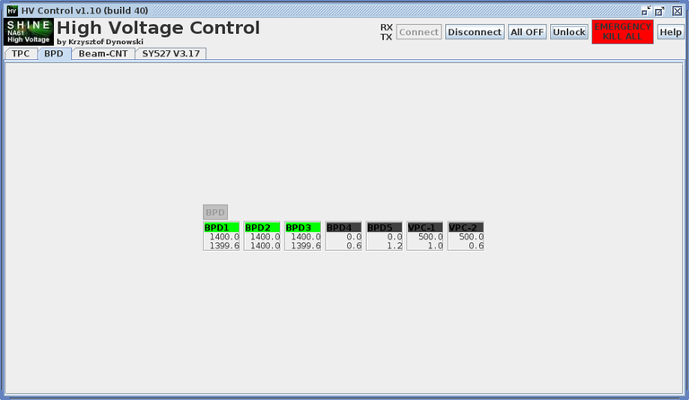
Tue, 22.11.2011 17:14:18 |
S. Pulawski | HV Setings of counter for 75A Gev/c Be beam. |
|
| Attachment 1: id114-2011-11-22-171449.png
|

|
| Attachment 2: id114-2011-11-22-171501.png
|
|
| Attachment 3: id114-2011-11-22-171507.png
|

|
| Attachment 4: id114-2011-11-22-171516.png
|

|
| Attachment 5: id114-2011-11-22-171522.png
|

|
| Attachment 6: id114-2011-11-22-171529.png
|

|
| Attachment 7: id114-2011-11-22-171535.png
|

|
| Attachment 8: id114-2011-11-22-171541.png
|

|
| Attachment 9: id114-2011-11-22-171547.png
|

|
| Attachment 10: id114-2011-11-22-171553.png
|

|
| Attachment 11: id114-2011-11-22-171559.png
|

|
|
113
|
Sat, 19.11.2011 19:48:50 |
S. Pulawski | Signal cabel of Z get sum. |
| Connected back to ADC. Not reason to be unconnected earlier. |
|
112
|
Thu, 17.11.2011 00:51:05 |
Z.Fodor | Added PSD summed analog signal to ADC |
| See: https://na61db.cern.ch:8443/elog/DAQ+logbook/19 |
|
111
|
Thu, 17.11.2011 00:48:21 |
Z.Fodor | Deadtime after CAMAC fast clear changed |
| See: https://na61db.cern.ch:8443/elog/DAQ+logbook/18 |
|
110
|
Wed, 16.11.2011 14:52:19 |
A. Aduszkiewicz | TPC HV |
Today, testing with the beam on, the HV in the GAP TPC has been increased to the nominal value. It could be still too low, since the CO2 content has been increased with respect to the proton run.
The voltages set are:
VTPC-1: 1210/1180V
VTPC-2: 1060V
MTPCs: 1060/990V
GAP TPC: 1120V |
|
109
|
Tue, 15.11.2011 22:55:09 |
A.Laszlo, S.Pulawski | Oscillation observed on the pedestal line of VTPC2-Sector4,6 |
| See: https://na61db.cern.ch:8443/elog/DAQ+logbook/17 |
|
108
|
Tue, 15.11.2011 04:29:21 |
S.Kowalski | Zdet delay |
| [sk] -. add delay to sum of Zdet signal, order in ADC sum 19, pmt1, 20, pmt2 21, sum with delay 22 |
|
107
|
Mon, 14.11.2011 11:43:26 |
A.Laszlo | Added Z-det signal to MTDC |
| See: https://na61db.cern.ch:8443/elog/DAQ+logbook/16 |
|
106
|
Sat, 12.11.2011 19:57:26 |
Z.Fodor, A.Laszlo | T0 change |
| See: https://na61db.cern.ch:8443/elog/DAQ+logbook/15 |
|
105
|
Sat, 12.11.2011 08:11:21 |
S, Kowalski | HV Quartz det |
| runs 14846-14851 HV q1 2000 q2 2025 |
|
104
|
Fri, 11.11.2011 02:43:25 |
A. Aduszkiewicz | TPC HV status |
Chamber voltages are 30V below the nominal value. I'm afraid to go higher, since I have no tool to verify the results (DAQ crashes a lot).
GAP TPC 150V below the nominal value. This is because occasionally I saw beam particles saturating ADCs of several adjacent pads. |
|
103
|
Fri, 11.11.2011 01:57:45 |
H.-J. Mathes | Beam counter settings |
01:50 (HJM) These are the settings for this night (and may be the near future, too)
Counter Voltage Threshold
S1-1 1980 493 mV (KFKI Disc)
S1-2 1760
S1-3 1890
S1-4 1690
S2 1900 143 mV (KFKI Disc)
S4 1700 149 mV (KFKI Disc)
V0 1840 294 mV (LeCroy 621CL)
V1 1770 287 mV (LeCroy 621CL)
Reading of 621CL is *10 and of KFKI Disc *3. |
|
102
|
Thu, 10.11.2011 12:33:06 |
H.-J. Mathes | Beam counter switch on |
12:30 (HJM) Switched on the beam counters, 100V below the nominal values (set value in the dialog)

            These settings are different to the recorded settings from pRUN recorded here:
            https://na61db.cern.ch:8443/elog/Experts+logbook/79

counter present (set)  pRun from Elog
  S1.1   2100 (2200)      2200
  S2     1890 (1990)      2000
  S4     1820 (1920)      1920
  V0     1840 (1940)      1920
  V1     1770 (1870)      1850

Thresholds still at the old values (checked with DMM) from pRun.

14:10 (HJM) correction, found settings for HI test Run of 2010 (2010-11-27 15:49 ++):
https://na61db.cern.ch:8443/elog/Experts+logbook/49

Here we had:
Time   Counter   voltage
18:51   S12       1740
        S13       1880
        S14       1750
        S2        1900
        S4        1700
19:41   S14       1700 V (from 1750)

Here is also some information (2010-11-27 07:31 ++):
https://na61db.cern.ch:8443/elog/Experts+logbook/48

17:15 (HJM) set HV to the following values:
Counter     Voltage
S1.1         2100V
S1.2         1780V
S1.3         1880V
S1.4         1700V
S2           1900V
S4           1700V
i.e. S1.2 - S1.4 are also on, no reduction to V* counter high voltages. |
|
101
|
Wed, 9.11.2011 21:25:37 |
Seweryn Kowalski | Z-det ADC Channels |
Z-det: Crate 17-8, slot 9, channel 7 - gas, 8 - quartz1, 9 - quartz2
Checktestbeam: channels: 19,20,21 |
|
100
|
Wed, 9.11.2011 18:36:56 |
A. Aduszkiewicz | TPC HV |
| Chamber voltages are now 100V below the nominal values. Currents are low. |
|
99
|
Wed, 9.11.2011 14:06:01 |
S, Kowalski | Z det |
The quartz Z0det was installed on the position. The 2 singals was send to the ACQ.
We finished the test with LED.
The main HV Zdet Q1=200V Q2=2035 |
|
98
|
Tue, 8.11.2011 12:32:12 |
A.Aduszkiewicz | TPC HV drift and chambers |
The drift voltage has been set to the nominal value in all TPCs:
VTPC-1: 13000V
VTPC-2: 13000V (using GAP TPC power supply)
MTPCs: 19000V
GAP TPC: 10200V (using VTPC-2 power supply).
Voltage on the sense wires has been set to 200V below the nominal value. |
|
97
|
Mon, 7.11.2011 12:10:54 |
A. Aduszkiewicz | GAP TPC drift voltage |
| GAP TPC drift voltage set to 5kV. Found out that the current indicator is faulty and tends to show 0 at low voltage settings. After increasing the voltage the current looks normal. |
|
96
|
Mon, 7.11.2011 11:39:35 |
A.Laszlo, S.Pulawski | TPC pedestal oscillation observed again, now in full VTPC2-Sector6 |
| See: https://na61db.cern.ch:8443/elog/DAQ+logbook/11 |
|
95
|
Sat, 5.11.2011 18:45:41 |
A. Aduszkiewicz | TPC drift voltage 5kV |
I increased TPC drift voltage to 5kV.
I realised that in the GAP TPC there is no current visible on the power supply. Maybe for GAP TPC cable was disconnected from the TPC? |
|
94
|
Fri, 4.11.2011 17:04:52 |
A. Aduszkiewicz | TPC drift voltage 1kV |
Set the TPC drift voltage to 1kV.
The reason for the problems with switching it on before was that the HV cables were not fully plugged into the power supplies. |
|
93
|
Wed, 2.11.2011 16:29:11 |
A.Aduszkiewicz | TPC drift voltage |
The TPC drift voltage is set to 5kV in all 5 TPCs.
It has been set to 1kV earlier today, but elog was not operational due to the power cut in the small counting house.
---=== Update ===---
Realised that the current is equal 0 in all TPCs. Also DCS measures no voltage. Maybe the cables are disconnected from the TPCs? Turning the drift voltage down to 0 just in case. |
|
92
|
Sun, 18.09.2011 20:33:05 |
A.Laszlo | PSD sum signal to ADC1-10 |
| We connect the PSD sum signal (arriving on S5 aircore cable) to ADC unit 1 (rack 17 crate 8 slot 8) channel 10. |
|
91
|
Fri, 16.09.2011 09:20:06 |
A.Laszlo | PSD trigger uses aircore cable of S5 temporarily |
| We unconnected S5 PMT from its aircore cable, and used it for PSD trigger signal line to shorten PSD delay. |
|
90
|
Mon, 5.09.2011 11:58:55 |
W. Dominik | VT-2 noise fighting - story continues |
During the SPS break an attempt to cure the noise (oscillations) in the sectors 1 and 6. Action:
1. contact-cleaner was put on the patch-box 1 and 6 connectors and on the box itself
2. Boxes 1 and 6 were wrapped with copper cord and connected to the ground
3. Boxes positioned to get the best possible contact with the top plate of the VT-2
On the pedestals taking seems that it helped. Should be confirmed with real data |
|
89
|
Mon, 5.09.2011 10:05:26 |
W. Dominik | VTPC-2 noise oscillations understood! |
From the beginning of the restart after the long MD a noise (oscillations) in the VTPC-2 sector 3 were observed. The reason was not understood. Many actions were taken mainly related to the LV crates (some listed below not in chronological order)
1. Carts 53 and 54 were replaced by spare ones
2. Displacment of the cards 52, 53 and 54 to the right side of the crate
3. Change of the top crate power supply
4. Swap of the powre supplies between the middle and top crate
5. Change of the power supply in the middle crate
6. A lot of power cycles
7. Contact-cleaner on the connectors ob the VT-2 Gating Grid (this made sense!)
None of these action really solved the problem in long term
The problem was understood by midnight 04/09 only.
The source of the problems are the transmission lines from the GG pulsers to the Gating Grid!
We (SP, OW and WD) entered to the VT-2 magnet from the top, found the GG lined Patch Boxes (only three of them are directly accessible - 1, 3 and 6; the other are hidden under the floor on the electronics). We shaked the boxes (contacts on the connectors and the placement. NOTE: the boxes are laying free - their are neither grounded nor isolated!
It helped for sector 3, but the sector 1 bezame a little noisy (sector 6 as well). It is better now, but we should still improve and stabilise the technical aspects of this (contact-cleaned and grounding(?))
We should do this by the next SPS break.
In the quiet time, when the floor over VT-2 can be removed all patch boxes should be checked and corrected! |
|
88
|
Tue, 23.08.2011 12:04:53 |
T. Matulewicz, P. Roznowski | MTPC L drift length change 2 |
| MTPC L drift length change 2 |
|
87
|
Mon, 22.08.2011 09:53:28 |
T. Matulewicz, P. Roznowski | MTPC L drift length change |
| MTPC L drift length change |
|
86
|
Wed, 17.08.2011 14:46:09 |
S. Pulawski | Change in HV channels... |
14:44 (sp) 4 new HV cabels and 3 signal cabels finded and changed to Z detectors.
Screens of old HV DCS monitor before change and after (M1 and M2 channels used now to Z detectors) |
| Attachment 1: id86-2011-08-17-144621.png
|

|
| Attachment 2: id86-2011-08-17-144650.png
|

|
|
85
|
Tue, 16.08.2011 17:37:20 |
A.Laszlo | Changed S5 HV to -1930V |
| Raised HV on S5 to -1930V to plateau it. |
|
84
|
Wed, 10.08.2011 14:35:21 |
A.Laszlo | Changing HV of S5 |
| Changed the original S5 HV -1820V (see: https://na61db.cern.ch:8443/elog/Experts+logbook/110810_143543/id84-2011-08-10-143537.png.png?thumb=1) to: -1870V (see: https://na61db.cern.ch:8443/elog/Experts+logbook/110810_184337/id84-2011-08-10-184333.png.png). |
| Attachment 1: id84-2011-08-10-143537.png
|

|
| Attachment 2: id84-2011-08-10-184333.png
|

|
|
83
|
Fri, 5.08.2011 11:35:02 |
A.Laszlo | MTPCL gating grid contact problem |
| MTPCL sectors 11-20 showed spike in the middle of time range. Rainer's advice was to check contacts of trigger LEMO cable to gating grid pulser. Intervention seemed to help. |
|
82
|
Thu, 4.08.2011 18:47:29 |
Z.Fodor, A.Laszlo | Modification of MTDC mapping |
| See: https://na61db.cern.ch:8443/elog/DAQ+logbook/5 |
|
81
|
Wed, 3.08.2011 20:03:59 |
Z.Fodor, A.Laszlo | Gating grid problem in VTPC2 repaired |
Gating grid pulser ringing was detected in VTPC2 sectors.
- Contacts were moved. This helped for all sectors, except for Sector4.
- Gating grid pulser of Sector4 was swapped with Sector3. Then all sectors were OK.
- When switching back Sector3 <-> Sector4 pulsers, the ringing on Sector4 came back.
- Finally we put pulser of Sector3 to Sector4 and put a new pulser to Sector3. In this state all sectors seem OK.
- Exact reason is not known. |
|
80
|
Mon, 1.08.2011 14:02:33 |
W. Dominik | Magnets V1 & V2 settings and callibration |
14:00 callibration:
V1 for I=5000A measured ==> should be 5000A set
V1 for I=3800A measured ==> should be 3828A set |